A frequent request has been that my SerialCommand library be usable with SoftwareSerial objects. I’ve never had a use for this myself, so I never tried to code anything for it. In order to test this I had to put a setup together where I could be reading/writing to a SoftwareSerial port and still have access to the hardware serial for debugging.
For this I used a CP2103 Breakout I bought a long time ago from Sparkfun and had sitting in a box. How old? It has a green-not-red circuit board, that should be an indicator. To make it more complicated I used an entire second computer connected to that CP2103 using our old friend Hyperterminal so I could debug it. I tested this on an UNO R3 and Arduno IDE 1.0.5.
This version is now on github. I have not tested it extensively, except to modify the included demo program to see that it works correctly with the SoftwareSerial line.
If you have trouble, be sure your SoftwareSerial ports are actually working the way you intend. The library includes a tiny test program that spits stuff out your SoftwareSerial port and your hardware serial port, so you can identify which one is which.
As a note, if you used this library before, you now have to include SoftwareSerial.h in your project, even if you’re not using it. Don’t blame me, blame the way the Arduino IDE compiler wants to preprocess things. You could also keep using the old version of the library, as there were no functional changes other than the SoftwareSerial support. Other than the include I don’t think it should have any effect on existing code.
I’ve written before about using an Atmel AVR Dragon to debug an Arduino board, using AVR Studio 4. I recently had some communication from Stephen Lake where he mentioned he was using Eclipse for Arduino development. I’d looked at Eclipse a long time ago and setting it up was an absolute terror with no real benefit. Stephen said it was much easier now, so I figured I’d have a look. Along the way I found the toolchain is robust enough these days to support DebugWIRE debugging of the Arduino and not have it suck too hard. I spent a lot of time trying to get the setup right, so I figured I’d detail it out if you’re trying to figure it out too, and save you the effort.
I’m standing on the shoulders of giants here. I’ve developed none of the software/plugins involved. I just put the pieces together from some disparate sources, some of which are a little out of date. The real credit goes to the authors of the software used in this. I did the setup on Windows and Linux, and the steps are 90% the same. I haven’t tried any of this out on OSX. This worked for me, maybe it will work for you. Maybe it won’t. I did this with Arduino IDE 1.0 installed.
Here’s what you’re going to need:
An Arduino that’s been modified for DebugWIRE operation
Eclipse
An AVR Dragon. Other debuggers might work, but a Dragon is what I have
WinAVR (Windows) or the AVR Toolchain (Linux)
libusb for Windows
Some patience. Okay, a lot of patience.
Get a DebugWIRE-capable Arduino
I wrote a whole big-ass article on this before, so you can reference that. For this experiment I used my modified Diecimila board. It will probably work with the UNO and other boards, I just haven’t tested them. Your mileage may vary.
Eclipse
More specifically, Eclipse IDE for C/C++ Developers (includes Incubating components). At the time of this writing Eclipse was 3.7.2. The nice thing about Eclipse is that it doesn’t have to be “installed” on your system, you can just unzip the folder and run it from that. That means you can keep many, many different versions of Eclipse configured for different tasks like I do around and not have to worry about trying something that will foul it up in some other aspect. I started out with the base CDT version and added into it. You’ll also need Java for this, of course, since Eclipse requires Java to run. Hey, I hear Eclipse can be used for Java development. groan.
On Ubuntu you can just apt-get it, but I chose to download and unzip it.
Atmel AVR Dragon
The dragon is (still) only $54 from Digikey in Canada. I’m sure you can get one just about everywhere. You can probably make all this work with the Atmel JTAG ICE III (I didn’t even know they had a III out), but those are expensive and so I don’t have one. You don’t have to do any mods to the Dragon other than maybe put some pin headers on it. I put a ZIF socket onto mine, but we won’t use it for this exercise.
AVR Dragon connected to Diecimila via ISP cable
WinAVR (ie – GCC Toolchain)
For Windows you want WinAVR. I used WinAVR 20100110 in this, and there’s nothing newer (and not likely to be anything newer). You might think that 2010 is old and you need something newer and cooler, but trust me working with the 20100110 is a lot easier than trying to build your own toolchain on Windows. When I started with this I had problems and I thought “a newer version might fix it”, and the problems just turned out to be me, and the building new stuff turned out to be a colossal pain.
You’ll also want some version of AVR Studio. In this I used 5.1 but I know it works with AVR Studio 4, since my previous article involved Studio 4. The thing to note is that v4.x and v5.x want different versions of the Dragon firmware, so if you want to go back and forth between 4.x and 5.x you’ll have to keep re-flashing the Dragon too. That’s a pain in the ass.
On Ubuntu you can just use the stock available AVR toolchain stuff,
As of this writing, the versions were gcc-avr (1:4.5.3-2), binutiles-avr (2.20.1-2), gdb-avr (7.2-1), avr-libc (1:1.7.1-2), avrdude (5.10-3), avarice (2.10-3ubuntu1). Like WinAVR, there are newer versions available but the stock ones worked (I did build avarice 2.12 to test, didn’t make any difference in what I saw). I also had the stock Ubuntu 11.10’s OpenJDK for Eclipse.
From here on out I’m going to stick to the Windows side of things, but really, if you use Ubunnnntu you’ll figure out how to set the right stuff in Eclipse, you’re smart like that.
libusb for Windows
Here’s where the pain in the ass really comes in. I spent the longest time trying to get this sequence of stuff right, and here’s what worked. This is the primary reason I wrote this article, because it was such an orderal figuring out the right way to make this all work correctly.
If you install one of your AVR Studio (v4 or v5), it will install the AVR Dragon USB driver. That’s great. The Dragon works fine in AVR Studio. Problem: nothing else will. The WinAVR stuff won’t talk through the Jungo driver to the Dragon. Instead, you’ll have to install libusb-win32 to provide an alternate usb access that the WinAVR stuff can work with.
Difficulty: when you install the libusb stuff, the Jungo driver is not active, and so AVR Studio doesn’t work with the Dragon. So if you’re like me and you keep popping back and forth between environments, you have to keep changing the driver. The good part is, it’s easy to do, it’s just busyness. There may be an alternate way to make this work, but I couldn’t find it.
So you need libusb-win32 for this. I used version 1.2.6. There is a version that comes inside the WinAVR directory itself, but I wasn’t successful getting it to work flawlessly. It probably does, but if so I wasn’t doing it right. I was able to do it right with the 1.2.6 version, so that’s what I’ll describe.
With AVR studio installed, and your dragon attached, you can check in the Windows device manager that you have a driver for “Jungo” in play, and the AVR Dragon is associated with it. Unzip the libusb-win32 stuff, and look inside for the “install-inf.exe” program. If you run that, this will make a very nice .INF style installer for your Dragon that uses the libusb driver.
Once you’re done you can push the “Install Now” button to actually install the driver.
From here on out, if you’re going to go back and forth between AVR Studio and the WinAVR-style toolchain you’ll have to learn how to switch between the Jungo driver and the libusb driver. It’s pretty easy. With your Dragon attached, bring up the device manager. Select whatever driver is currently installed, right-click and select “uninstall.” Don’t worry, this doesn’t remove anything, the driver sticks around on your computer. The driver will disappear from the device manager list. Unplug and re-plug in your Dragon via USB and you’ll see the Windows “found new hardware” message. Walk through the Install New Hardware wizard, but don’t let it automatically install anything. Choose “Install from a list or specific location”, and “Don’t search. I will choose the driver to install.” Then you’ll get to pick between the Jungo driver and the libusb driver.
Verify Dragon Operation with Jungo and libusb drivers
AVR Studio
Before you go any futher, you should verify that you can get your Dragon to work in AVR Studio and the WinAVR toolchain. Switch to the Jungo driver, start up AVR Studio, and start up the “AVR Programmer”.
You should be able to connect to your Dragon, and read the fuses on the chip. The nice thing about AVR Studio 5.1 is the programmer will tell you the correct chip if you’ve picked the wrong one. On my Diecimila it’s an ATMega168.
NOTE THE FUSE CONFIGURATION. Messing up the fuses is the easiest and fastest way to making your Arduino experience unhappy. We’re going to be changing some fuses during the course of debugging, so you’ll have to learn how to put all the fuses back correctly when you’re done. If you screw up the fuses, the on-board Arduino bootloader will not work correctly. Also note that the fuses are different for the different Arduino models. The ones I show are for my Diecimila. The ones on the UNO are set differently.
Also, you can use the AVR Studio programmer to burn the bootloader back to the Arduino in the event you mangle things up pretty good. This is useful since the Arduino IDE will let you burn the bootloader with a variety of devices but the Dragon is not one of them. Remember to choose the right bootloader for your chip for pity’s sake.
AVRDUDE and libusb
With your Dragon connected, and connect to your modified-Arduino via the ISP cable, switch over to the libusb driver as described earlier. Open up a command prompt (Start -> Run -> cmd). The main command-line program from WinAVR we’ll use will be AVRDUDE. WinAVR sets that PATH variable, so you can type avrdude commands from any directory.
Easy: Check to see that your dragon even responds. Use dragon_isp with avrdude:
avrdude -p atmega168 -c dragon_isp -Pusb
You should get something like this:
avrdude: AVR device initialized and ready to accept instructions
Reading | ################################################## | 100% 0.17s
avrdude: Device signature = 0x1e9406
avrdude: safemode: Fuses OK
avrdude done.  Thank you.
Sometimes you have to hit the command a couple of times before the Dragon will start talking. You’ll hear windows make that little “dunk” sound as the Dragon resets itself, and if you try to avrdude it too quickly it won’t respond correctly. With the libusb driver installed and set to be the current driver you can unplug/replug as much as you want and it’ll always use the libusb driver. It won’t go back to Jungo unless you uninstall the libusb one and switch back manually.
If you get something like this:
avrdude: Version 5.10, compiled on Jan 19 2010 at 10:45:23
         Copyright (c) 2000-2005 Brian Dean, http://www.bdmicro.com/
         Copyright (c) 2007-2009 Joerg Wunsch
         System wide configuration file is "C:\WinAVR-20100110\bin\avrdude.conf"
         Using Port                    : usb
         Using Programmer              : dragon_isp
avrdude: usbdev_open(): did not find any USB device "usb"
That means you have usb issues. Check that the libusb driver is being used. Try replugging your Dragon and see if that helps.
For even more detail, use the -v flag on avrdude:
avrdude -p atmega168 -c dragon_isp -Pusb -v
You’ll get reams of data. Remember, this is for the Diecimila with the ATMega168. If you have an UNO or a Mega or something with the ATMega328 your results will be different.
avrdude: Version 5.10, compiled on Jan 19 2010 at 10:45:23
         Copyright (c) 2000-2005 Brian Dean, http://www.bdmicro.com/
         Copyright (c) 2007-2009 Joerg Wunsch
         System wide configuration file is "C:\WinAVR-20100110\bin\avrdude.conf"
         Using Port                    : usb
         Using Programmer              : dragon_isp
avrdude: usbdev_open(): Found AVRDRAGON, serno: 00A200011176
JTAG ICE mkII sign-on message:
Communications protocol version: 1
M_MCU:
  boot-loader FW version:        255
  firmware version:              7.21
  hardware version:              1
S_MCU:
  boot-loader FW version:        255
  firmware version:              7.21
  hardware version:              7
Serial number:                   00:a2:00:01:11:76
Device ID:                       AVRDRAGON
         AVR Part                      : ATMEGA168
         Chip Erase delay              : 9000 us
         PAGEL                         : PD7
         BS2                           : PC2
         RESET disposition             : dedicated
         RETRY pulse                   : SCK
         serial program mode           : yes
         parallel program mode         : yes
         Timeout                       : 200
         StabDelay                     : 100
         CmdexeDelay                   : 25
         SyncLoops                     : 32
         ByteDelay                     : 0
         PollIndex                     : 3
         PollValue                     : 0x53
         Memory Detail                 :
                                  Block Poll               Page                       Polled
           Memory Type Mode Delay Size  Indx Paged  Size   Size #Pages MinW  MaxW   ReadBack
           ----------- ---- ----- ----- ---- ------ ------ ---- ------ ----- ----- ---------
           eeprom        65     5     4    0 no        512    4      0  3600  3600 0xff 0xff
           flash         65     6   128    0 yes     16384  128    128  4500  4500 0xff 0xff
           lfuse          0     0     0    0 no          1    0      0  4500  4500 0x00 0x00
           hfuse          0     0     0    0 no          1    0      0  4500  4500 0x00 0x00
           efuse          0     0     0    0 no          1    0      0  4500  4500 0x00 0x00
           lock           0     0     0    0 no          1    0      0  4500  4500 0x00 0x00
           calibration    0     0     0    0 no          1    0      0     0     0 0x00 0x00
           signature      0     0     0    0 no          3    0      0     0     0 0x00 0x00
         Programmer Type : DRAGON_ISP
         Description     : Atmel AVR Dragon in ISP mode
         Vtarget         : 5.0 V
         SCK period      : 8.00 us
avrdude: AVR device initialized and ready to accept instructions
Reading | ################################################## | 100% 0.16s
avrdude: Device signature = 0x1e9406
avrdude: safemode: lfuse reads as FF
avrdude: safemode: hfuse reads as DF
avrdude: safemode: efuse reads as 0
avrdude: safemode: lfuse reads as FF
avrdude: safemode: hfuse reads as DF
avrdude: safemode: efuse reads as 0
avrdude: safemode: Fuses OK
avrdude done.  Thank you.
Remember our little talk about fuses earlier? Take note of your fuse values (in my case, FF DF 00), as you’ll need them later to reset stuff. You can choose to have avrdude write them to a file, but it’s also good just to make a note somewhere.
If your Dragon talks to avrdude correctly with the libusb driver, you’re all set. Practice going back and forth between AVR Studio configuration and avrdude configuration for your Dragon.
Where the ATmegaBOOT_168_diecimila.hex is from the arduino bootloader directory in the Arduino IDE tree (in Arduino-1.0’s case that’s arduino-1.0\hardware\arduino\bootloaders), pick the right bootloader for your chip. Remember your fuses are probably different. Which is why it’s good to use AVRDUDE or AVR Studio to find them out and write them down before you mess with anything. The ultimate reference is your arduino boards.txt (arduino-1.0\hardware\arduino\boards.txt). If you’re too lazy to look there, there is this reference as well, but I note that one of my fuses is slightly different in my Diecimila. Look up what all the fuse codes do if you’re concerned.
AVRDUDE will erase all the flash as a feature of doing this, so if you had an arduino program on the chip it will also be gone when you re-flash the bootloader. When the Arduino is “empty” it sits there flashing the LED (pin 13) on the arduino board on and off.
This is the reason that this whole post is even possible. It used to be a huge pain in the ass. No stop, don’t do anything that article says. Instead take the advice at the top of it and go get this plugin instead. The full installation instructions are there on that nice person’s site. Thanks very much for that.
In short: in Eclipse, choose “Install new software”, enter his plugin repository address, and add the latest version of the plugin (1.2.1 as of this writing).
Now at this point you’re all set to do Arduino development in eclipse. You can write code in Eclipse, and upload it in Eclipse (via avrdude). There are some differences between doing development in Eclipse vs. doing it in the Arduino IDE. If you’re new to Eclipse you’ll find it has a shit-tonne of features and things that make you scratch your head. Also, code you develop has to be modified slightly to conform to the Eclipse CDT standards. This is detailed in the baeyens.it instructions. In particular Eclipse will throw out tons of warnings you never knew about for code that works fine in the Arduino IDE, because the Arduino IDE is set to compile with the warnings off. Warnings on is helpful if you’re trying to figure out problems, but if you’re new to the whole coding scene it will probably be pretty daunting to wrap your head around them. Also, the Eclipse ide still requires prototypes for functions, which if you’re written functions in the Arduino IDE you’re probably asking “What are prototypes?” I wouldn’t call using Eclipse for Arduino development a beginner’s task. Learn to do stuff with the Arduino IDE first. Again, the reason I’m writing this is because we want to move on to doing hardware debugging with Eclipse.
Install GDB Hardware Debugging into Eclipse
Most of this is similar to this setup for doing debugging with basic AVR chips, and not specific to the Arduino. I’ll give some specific setup points for integrating this with the Arduino plugin.
Here’s some more magic install stuff. In Eclipse “Install New Software”, and you can select “Work With: all available” sites. You will see a staggering amount of extra stuff you can install into Eclipse, only a fraction of which I even know what it does. What you’re looking for is GDB Hardware Debugging, so you can enter “gdb” into the filter box, and it will narrow the list down.
I didn’t install SimulAVR (the simulator), because I didn’t care about that. I also didn’t set up AVARice as an Eclipse “external tool” because quite frankly figuring out this debugging setup was more difficult that way. I found it much easier just to rely on running the WinAVR tools from an open command-line window.
Most of the settings are project dependent, so you’ll have to set them every time you start debugging a new project in eclipse, so I’ll go through that using some demo code.
A Simple Project in Eclipse
First off, make a new Arduino sketch in Eclipse using the Arduino plugin instructions. (File -> New Project)
Note that this will make two projects in your Eclipse tree. One for your test project, and one which contains the core Arduino code in a separate project meant for your specific Arduino board. In my case, the Diecimila. I called my project “ArduinoDebugTest.”
In the ArduinoDebugTest.cpp file, let’s use this code:
// Do not remove the include below
#include "ArduinoDebugTest.h"
#define LEDPIN 13
//The setup function is called once at startup of the sketch
void setup()
{
// Add your initialization code here
    pinMode(LEDPIN,OUTPUT);
    Serial.begin(9600);
}
// The loop function is called in an endless loop
void loop()
{
//Add your repeated code here
    digitalWrite(LEDPIN,HIGH);
    digitalWrite(LEDPIN,LOW);
    delay(1000);
    digitalWrite(LEDPIN,HIGH);
    Serial.println("I turned the LED on, off, and on again");
}
This code is pretty simple, because all we want is something simple we can use with the Dragon debugger to see that it works. It’ll flash the LED on the arduino board, then print something via the Serial porn on the Arduino.
Build this code with Eclipse (there are many ways to do this, including the little hammer icon on the toolbar, also right-clicking on the project). You’ll see in the console lots of messages go by as it builds the Arduino Core and then builds your program. If everything works out the final message will include the size of your code:
That should look at least partially familiar, since the Arduino IDE also reports a size when it’s done compiling. Connect your Arduino board via USB to your computer and upload the code with Eclipse (the AVR upload button). Note that the Arduino Plugin very nicely sets up avrdude for you for the upload.
Here’s a fine point to remember: because you’ve modified this Arduino board to work with DebugWIRE, you’ve also lost the ability for avrdude (and the Arduino IDE, which uses avrdude) to auto-initiate the upload. So you have to be quick and push the reset button on the Arduino board when you start the upload. That will trigger the bootloader to look for a new upload for a couple of seconds, then it starts your on-chip arduino program. Timing is important. I find I can push the “AVR Upload” button, then immediately push the reset on the Diecimila and the upload works fine. You can see it works if the TX/RX led’s on the Arduino furiously light up for a few seconds. With the Arduino 1.0 IDE your timing has to be more precise because the IDE always does a build before the upload, so you have to wait until the build part is done – push the reset button – and then catch when the IDE’s upload starts. Also, in Eclipse you’ll see some status messages in the Console saying the upload is working and finishes.
After the upload finishes you should see the Arduino LED start to flash. Then start up the Arduino IDE’s serial monitor (or your favourite terminal program that you know how to get to talk to the Arduino’s usb-serial), and you should see this:
Congratulations, you’ve successfully gotten the code-edit-build-upload workflow working. Now the real fun starts. You can actually stop here and happily continue on your life using Eclipse for Arduino development and never have to bother yourself with hardware debugging.
Build your project with Debugging Info Available
With Eclipse, normally you have build configurations for “Release” and “Debug” versions. When you build for debug the compiler adds in extra symbols and shit which the debugger (GDB) uses to figure out just what the heck is going on in your compiled code, and trace that back to what the source code was.
I had issues making a “Debug” build configuration work with the Arduino plugin, and I think it’s because of the separate project for the Arduino Core that has to be compiled against. Headers would get confused and code wouldn’t build (“pins_arduino.h” kept getting involved, so something was wrong). So in the end I just elected to turn on debugging in the Release configuration and it works fine. The Arduino IDE normally does build things in debug mode (-g), and I think from the output the Arduino Eclipse Plugin is the same, so this may not make any difference – but I set some options to be sure.
In the properties for your project (not preferences for eclipse – these properties are stored for each project), go to the C/C++ Build Settings, and in the Release configuration (the only one which should be there) you want to turn on debugging information.
Normally it looks like this by default:
Change it to “Standard debugging info -g2” and “stabs (avr-gdb / insight)”. Do this for both “AVR Compiler” and “AVR C++ Compiler” to be sure.
(This may not make any difference, as the Arduino Plugin is already setting flags, but this makes me feel better).
After this you should rebuild your program, and upload it to the Arduino over the USB port.
If you have consistency problems with building, trying doing the “make clean” before rebuilding, as that will make it recompile everything. Computers are fast, you can wait the ten extra seconds.
Put Arduino chip into DebugWIRE mode
This is pretty easy, but very important. The Dragon can only debug in debugwire if debugwire is turned on in the AVR chip (duh). Problem is when debugwire is active SPI is not available, so you can’t leave debugwire on all the time. So get used to putting it in and out of debugwire mode.
To set debugwire mode, the easiest way in this workflow is to use avrdude to set the appropriate fuse. You can use the fuse calculator in eclipse, or one of a million online ones. You can also use AVR studio, but if you do this you’ll have to pop back to the Jungo USB driver, then back to the libusb driver to get anything more done.
In my case, the Diecimila’s regular hfuse setting is 0xDF (we saw that earlier with avrdude, remember?). To enable DebugWIRE the hfuse setting has to be changed to 0x9F. Use avrdude to change it:
You may have to do the operation twice, as avrdude might have trouble on the first pass and ask you to redo the command without powercycling. There is a “-c dragon_dw” mode you can use, but I find that avrdude is smart and notices the dragon is in Debugwire mode and switches as needed.
After you change the debugwire fuse state, you have to power-cycle your Arduino. You also might as well power-cycle the Dragon itself, since I have much more “first try worked” success if both get power-cycled.
Once you’ve enabled the debugwire fuse, the Arduino’s on-board bootloader will not work. SPI is disabled and so the bootloader doesn’t function correctly. So make sure you’ve got the correct code uploaded before you enable debugwire. Otherwise you’ll have to disable it, upload, then re-enable it.
Hardware GDB Debugging with the Dragon
If you found the stuff up until now not complicated enough, this probably will satisfy you. What we’ve done up until this point is essentially the same workflow as the Arduino IDE does. What we’re going to have to do now is change the build process slightly in order to accommodate GDB, which is the program behind all the debug session stuff we’re about to do. Then we’re going to find a really big pitfall, but more when we get to that.
Debugging is accomplished through GDB. Eclipse talks to GDB. GDB knows how to talk to AVARICE. AVARICE is the program that knows how to run DebugWIRE on the AVR Dragon. The Dragon is the board that talks via DebugWIRE over the ISP cable to control the execution of code on the Arduino board. Make sense? We have to get all these layers to talk to each other correctly or none of this shit works.
We’ll start on the Eclipse end. Start by making a new “Debug Configuration” in Eclipse (click the arrow next to the little picture of the bug, a couple of squares to the right of the hammer… sigh). A dialog starts up with a bunch of C/C++ options on the left side. Click and add a new configuration on the one called “GDB Hardware Debug”
Then we’re going to march through the tabs on this debug configuration.
First thing is in the “Main” tab to pick your .elf file, which is the compiled code used by the debugger which has all the symbols and shit in it. When I use this with the standard AVR development plugin it auto-inserts the proper .elf file for me, but with the Arduino plugin you have to navigate to your Arduino Eclipse workspace and select the .elf by hand. No big deal.
Set your GDB command to be the avr-gdb.exe in the WinAVR directory. You need to change the preferred launcher to the “Standard GDB Hardware Debugging Launcher” down at the bottom of the dialog window. I couldn’t make this work with the DSF launcher. You can tell you’ve got the right one because it has the option for “protocol version: mi” as shown. I change the port number to 4242, only because the original AVR Debugging article does that.
Then in the “Startup” tab have the setup as shown. Note this is different than the AVR debugging article setup. In particular rather than break on “main” we’re going to break on “setup” since in the Arduino version of the world the “main” is hidden. Turn off reset, halt, and load image (I couldn’t get it to work anyway). Turn on load symbols. I don’t make any changes in the next two tabs (source, common) so you can leave those as is.
Once you’ve got all the settings done, you can click “Apply” and close the dialog. Don’t bother trying to start “Debug” yet, because we need to get AVARICE running.
Running AVARICE is pretty easy. In a command window:
avarice --debugwire --dragon --ignore-intr :4242
If your Dragon is connected properly, you have libusb active as the driver, and your chip is in DebugWIRE mode. you’ll see this:
AVaRICE version 2.9, Jan  7 2010 22:42:57
JTAG config starting.
Found a device: AVRDRAGON
Serial number:  00:a2:00:01:11:76
Reported debugWire device ID: 0x9406
Configured for device ID: 0x9406 atmega168
JTAG config complete.
Preparing the target device for On Chip Debugging.
Waiting for connection on port 4242.
If you get an error, check that you’re using libusb. Also in most cases just cycling the power on both the Dragon and the Arduino puts it back to working. If you give avarice a -v flag for verbose it will constantly spit shit out for you to read and not be interested in as you debug.
Are we there yet? Start the Debug Session
Okay, with your eclipse debug configuration set, debug-enabled code uploaded to the arduino, debugwire enabled, and avarice up and running and waiting for a connection, it’s time to start up the debugger. Click the little bug and select your debug configuration. It will want to change “perspective” on eclipse to show the debug windows, go ahead. It’ll also rebuild your code, but don’t worry about that, since it should be the same version that’s on your arduino already (right?).
if you look at your command window, you should see AVARICE has hooked up with GDB:
Connection opened by host 127.0.0.1, port 4951.
and ta-dah, that’s really it. Because you set the breakpoint for “setup” the code initialized and stopped at the beginning of your setup() routine. Now you can use the single-step commands in the toolbar to march through your code. When you end your debugging session AVARICE will quit, so you need to restart that before you restart debugging. The chip will remain in debugwire mode so you’re all set.
So now, you’re debugging, is it what you expected? Arduino’s success as a platform comes from the fact that the hardware is cheap, the IDE is easy to use, and the Arduino Core is a shitload huge library of awesome functions that make coding for it easy. If you use the “step into” command you’re going to be buried under the mountain of code that goes together to make your own Arduino code run, which will get pretty tedious, and you normally don’t have to debug yourself anyway. Also, timing based things (delay(), sending serial stuff) is going to get seriously broken if you try single stepping through it. Your friend in these cases is the “step over” command in the toolbar, which essentially says “run this whole command, including any subroutines, and come back after you’re done since I don’t want to see any of that single-stepped”.
As the exercise, you can single-step (step into/step over) until you get into your loop() routine, and then you can use step-over each of the digitalWrite() commands, and you should see the light on the Arduino change accordingly. When you hit the delay() and the Serial.print() you’ll want to use step-over unless you’re not bored enough single stepping.
You can set breakpoints and use the “resume” toolbar icon to say “just run until this line gets hit, then I’ll start stepping”, which can be useful if you have a lot of code that runs before your routines you want to debug are executed.
You’ll find your code keeps jumping out to this previously-hidden main() routine, which is how C/C++ actually works, so you just have to step through that back into your loop() code each time.
Also debugwire disables SPI, so if you were hoping to use this to check SPI hardware, I’m afraid you’re out of luck. Back to Serial.print(), or using something like a logic analyser (I have the Salae one).
To get back out of debugging, there’s a red button on the toolbar called “terminate”.
Note that when single-stepping it can take a seemingly long time between steps, because GDB/AVARICE/Dragon is doing a lot of talking amongst themselves getting status from your chip. I believe every time the single-stepper stops the Dragon dumps the entire contents of the Arduino’s ram for display by GDB/Eclipse. You do get lots of fun light flashing on the Dragon during all this, though.
Optimization Can Be a Bitch
The sample program above didn’t have any variables, on purpose. When you’re debugging in Eclipse one of the windows shows the variables in your program, which is – in my opinion – the best part of debugging. It lets you spy into the variables and see if variable “a” is really holding what you think it’s holding. I didn’t use any variables for illustration above because it wouldn’t have worked right, here’s why, and here’s how you work around that.
The Arduino is an embedded platform with limited ram and storage (flash). The Arduino people (correctly) turned on size optimization in the Arduino’s compiler. Optimization is big topic in compiler design, and it essentially boils down to “the user wrote this code to do this task, and as the compiler I will re-write it to make it work faster/better/smaller”
The problem with debugging optimized code is that… well, it’s different code than what you wrote. In particular, the size optimizer (-Os) on GCC will do some amazing stuff like “you set this variable, and never used it, so I removed all references to it from the actual compiled code.” There’s also the general case of “oh, you didn’t have a lot of variables, so instead of keeping them in ram I kept them in registers instead for easier access.” Variables held in registers tend not to show up in the “variable” window so you can’t spy on them, you have to go look at the registers directly.
Let’s do a little experiment to show this. Make a new Eclipse Arduino Sketch called ArduinoOptimizerTest and use this code in your .cpp file:
// Do not remove the include below
#include "ArduinoOptimizerTest.h"
//The setup function is called once at startup of the sketch
void setup()
{
    Serial.begin(9600);
}
// The loop function is called in an endless loop
void loop()
{
    int a;
    int b;
    a=25;
    b=a+a;
    Serial.print("a is ");
    Serial.println(a);
    Serial.print("b is ");
    Serial.println(b);
    delay(1000);
}
Now this is a damned boring program. It stores a number in a variable, does some math, and prints it out. Yawn. You don’t need an Arduino for this, but we will do this to show just how much the Optimizer works to make you a better person. To show we’re not cheating, build this with the debugger info set, load it onto your arduino, and check it with the serial monitor to see that it does give output. (“a is 25” “b is 50” over and over).
Easy, it worked, right? This is a stupid experiment, right? So now go into debugging mode with the Dragon. Put the chip into debugwire mode, do a debug config, and start debugging in Eclipse and have a look at what’s going on.
Oh shit, check it out. See when you ran your program and single stepped it… it never ran the a=25 / b=a+a lines, for some reason the single step went right over them to the Serial.print() line. Why did it do that? Well, check the disassembly window on the right hand side. The Disassembly is the “these are the actual machine code instructions GCC compiled your code into and are running on the Arduino.” It’s a lot of strange looking little single-purpose instructions but you can see how your code has been translated into the machine code.
See how it says “loop:”, a couple of push r16/push r17 and then the instruction pointer for “Serial.print” is that “ldi” instruction? The GCC -Os optimizer said “you know what, you set those a and b variables, but never actually use them other than to do that print, so we just skipped all that and moved it all into the print call itself. The code was simple enough that the optimizer optimized it all away. The results are the same, but the execution is different than you expected.
Note that this is not actually a problem, this is a good thing. It means the compiler is looking out for you and trying it’s damnedest to make your code fit in the limited Arduino space and still do everything you want. It does mean that if you’re stepping through the code you may get surprised.
As an aside, many many many years ago when I was writing unix code on Sun systems you could not debug optimized code at all with the debugger. You had to debug with the un-optimized code only. So if you had a bug that showed up when optimized, but not when un-optimized, you were really shit-outta-luck. It was the best thing evar(tm) when GCC started doing enough work to let you debug stuff that had been mangled by the optimizer.
So okay, as an academic exercise now, what if you want the “pure” code you wrote to debug, and not the optimized version? Easy. We go back into the project properties and turn off the optimizer (-O0 instead of -Os for both the AVR Compiler and AVR C++ Compiler).
Then you have to rebuild – right click your project and do “make clean” first, to make sure all the code gets rebuilt without optimzations. When your build finishes you’ll see that sure enough, your code is larger than when it was built with -Os. You could get a problem where the code could be too big to fit in your Arduino, but in this test case it’s still okay. Upload the code to your Arduino (remember you’ll have to take it out of debugwire mode to do that, then re-enable debugwire again), start up AVARICE, start up the debugger, and here’s what you’ll see:
See that the instruction pointer will actually be able to land on the “a=25” line, and the disassembly shows that there’s actual code assigned to it now. You can also see the disassembly directly for each of the instructions that follow (a shit load of instructions to do something that seems simple, isn’t it? This is why the optimizer works so hard for you).
In the two screenshots you can also see that “a” and “b” were set to some random values before being initialized, which is the reason you initialize variables.
Remember to re-build your projects with optimization on (-Os) again if you’re going to continue.
If you’re doing all this on Linux, you don’t have to worry about the libusb steps, since avrdude/avarice work on linux just fine with the default ubuntu install. Also there’s no AVR studio for linux, so hey, no having to deal with that end at all. Just remember how to set your chips back to factory with avrdude if you mess things up.
Condensed Version
Write Code in Eclipse, build without errors
Upload to Arduino over usb-serial in Eclipse
Enable DebugWIRE on Arduino with AVRDUDE
Start AVARICE
Configure and start up debugging in Eclipse
Debug until your eyes cross
Disable DebugWIRE when done
Summing Up
So this works for me, maybe it will work for you. Is it easier than debugging using my previous method with AVR Studio? I guess that depends on how much you like Eclipse.
Is this any better than debugging using AVR Studio? Not sure on that one yet, I’m still investigating doing the debug with AVR Studio 5.1. Certainly less toolchain setup in that case. Using Eclipse in the mix does give you better diagnostics on code errors than using the Arduino IDE, at the cost of more complexity.
Is any of this easier than just using Serial.print() statements? Hell no. But if you really can’t figure out why something’s not right, this might be the best way.
Finally, here’s another Arduino picture, as required by law.
At that time I mentioned the TTS256 chip from Sparkfun, which is essentially a little text-to-speech dictionary chip made to work with the Speakjet. You pump in some regular boring text over the serial connection to the TTS256, it converts it to that phoneme stuff and presto, the chip speaks.
At the time I did that previous post I didn’t have a TTS256, but now I do. Sparkfun have a very nice tutorial on how to wire up the chip into your Speakjet shield. That tutorial is really good, and has demo code and so I will repeat none of it here.
I followed the instructions as shown and had no problems, but the difference to what I did is that rather than solder the speakjet onto the shield, I soldered on a 24-pin socket (technically two sockets, since I didn’t have a 24-pin, but the effect is the same). The advantage of doing things this way is that if you want to go back to the ‘old’ way of using the Speakjet – in direct phoneme mode – all you have to do is jumper two areas in the socket and it works as it did before you ruined it.
Seriously, always use a socket with a through-hole part if you can get away with it. Makes replacing the chip a dream when you blow it up.
I have the ‘newer’ version of the board which has the surface-mount version of the speakjet (the tutorial has the through-hole version), but the pins are the same so the locations of the solder points don’t change.
Also, the sparkfun pictures are good but aren’t so clear where the connections are, so I tried to take some clearer pictures.
I discussed the Sparkfun Voicebox Shield in a previous entry, and also as a component of that same project I purchased a Seeeduino Relay Shield. Sure, normally I’d just hack up my own PCB for something like this, but it was only twenty bucks and I’m pretty sure I couldn’t build something comparable that cheap and get it that fast.
The relay shield has four relays that are optoisolated, which is a damned useful thing to have when working with 120 volt switching systems, as it lessens the odds of you accidentally turning your microcontroller board into a little charred pile.
This board also has an XBee socket on it, which I was singularly uninterested in, as I don’t have any XBee stuff.
The Seeeduino relay shield is pretty simple in operation: four relays are controlled by four of the digital lines on the Arduino. Nothing simpler. Assert the digital line on the Arduino, and the relay closes. Each of the relays has a NO (normally open) and NC (normally closed) connection, so you can use them in either orientation for your switching logic.
Given how basic this hardware is, it seems pointless to write an encapsulating class library to handle them. So I did it anyway. When you’re writing software projects it’s nice to do something “small” and “easy” to remind yourself of how things go together. So this library serves more as an example of how to write other libraries. The Arduino Playground has an example showing how to write a library, but this is a complete code example that’s actually useful (cough). Rather than being a library that you have to copy over to your Arduino user Libraries folder, this is all encapsulated as a multi-file (multi-tab) sketch, so you can view all the files at once. Plus, from the hate mail I’ve received it seems some people have problems figuring out how to install an Arduino library.
Although this is written with the Seeeduino in mind, the hardware is so generic I figure it should work for any relay control situation, just change the pins. Its purpose is to make reading code involving relays easier (encapsulation).
Since a relay is either “on” or “off” (and whether that’s open or closed depends on whether you use the the NO/NC connection), all you really need is:
Function to turn the relay on
Function to turn the relay off
Function to return the state of the relay (on/off)
A housekeeping variable holding the state (private)
Bonus: a function to toggle the relay state between on and off, based on what state it was in
You can probably think of a million more complicated functions this absolutely must have. I couldn’t. There’s no XBee support in this library, because there are libraries already for that. Also, I don’t have an XBee to test with.
The library code itself doesn’t use it, but the demo sketch uses the Bounce library, which is a generally useful library for handling buttons in your sketch.
Here’s SeeeduinoRelay.h, which has the class definition.
#ifndef SEEEDUINORELAY_H
#define SEEEDUINORELAY_H

#include "WProgram.h"

// These are the pins that control the relays on the Seeeduino board.
// If you are modifying this to work with different relay configurations,
// these are the pins you need to change.
#define RELAY1PIN 7
#define RELAY2PIN 6
#define RELAY3PIN 5
#define RELAY4PIN 4

// Class Definition.
class SeeeduinoRelay
{
public:
  SeeeduinoRelay(int RelayNum, int state);    // Constructor
  void on();    // Turns relay on
  void off();   // Turns relay off
  void toggle();  // Toggles state of relay between on and off
  int state();    // returns state of relay (LOW/0/off or HIGH/1/on)
  int isRelayOn();   // Returns TRUE if the relay is on , false otherwise
  int isRelayOff();  // Returns TRUE if the relay is off, false otherwise

private:
  int relayState;     // Variables holds on/off state of the relay
  int relayPin;       // Variable holds which Arduino pin connected to relay.
};

#endif   // SEEEDUINORELAY_H
and here’s the SeeeduinoRelay.cpp, which has the implementation:
#include "WProgram.h"
#include "SeeeduinoRelay.h"

//
// The constructor sets up a single relay, specified by RelayNum
// Which is relay 1,2,3 or 4 as specified on the Seeeduino Relay board
// "state" is the initial state (LOW or HIGH)
//
// Relay Truth Table:
// State     NOx    NCx
// LOW       open   closed
// HIGH      closed open
//
// The constructor will also properly set the assigned pin to OUTPUT.
//
SeeeduinoRelay::SeeeduinoRelay(int RelayNum, int state)
{
  if (RelayNum == 1)  relayPin=RELAY1PIN;
  if (RelayNum == 2)  relayPin=RELAY2PIN;
  if (RelayNum == 3)  relayPin=RELAY3PIN;
  if (RelayNum == 4)  relayPin=RELAY4PIN;
  pinMode(relayPin, OUTPUT);

  if (state == LOW) {
    relayState=LOW;
    off();
  }
  else {
    relayState=HIGH;
    on();
  }
}

// Turns the relay on.
void SeeeduinoRelay::on()
{
  digitalWrite(relayPin, HIGH);
  relayState=HIGH;
}

// Turns the relay off.
void SeeeduinoRelay::off()
{
  digitalWrite(relayPin, LOW);
  relayState=LOW;
}

//Toggles the state of the relay
void SeeeduinoRelay::toggle()
{
  if (relayState==HIGH) {
    off();
  } else {
    on();
  }
}

// Returns the state of the relay (LOW/0 or HIGH/1)
int SeeeduinoRelay::state()
{
  return(relayState);
}

// If the relay is on, returns true, otherwise returns false
int SeeeduinoRelay::isRelayOn()
{
  if (relayState==HIGH)
    return true;
  else
    return false;
}

// If the relay is off, returns true, otherwise returns false
int SeeeduinoRelay::isRelayOff()
{
  if (relayState==LOW)
    return true;
  else
    return false;
}
Here’s the demo sketch that ties it all together:
// This simplistic program demonstrates the use of the SeeeduinoRelay
// library with an Arduino.   Pushbuttons are connected to
// pins 8/9/10/11 for toggling relays on and off.
//
// [arduino button pin --------Switch------- GND]
//
// Internal Pullup resistors are activated on input pins.
//
// Note: Seeeduino has THREE e's, not two as you might think.  Check that
// first when trying to find unresolved references.
//
// Shield details:
// http://www.seeedstudio.com/depot/relay-shield-p-693.html?cPath=132_134
// http://garden.seeedstudio.com/index.php?title=Relay_Shield

#include <Bounce.h>    // http://www.arduino.cc/playground/Code/Bounce
#include "SeeeduinoRelay.h"

// Pin definitions for four buttons connected to the Arduino for testing.

#define Button1pin 8
#define Button2pin 9
#define Button3pin 10
#define Button4pin 11

// Define "bounce" objects for input buttons.
// Bounce is really nice, you should use it.
// http://www.arduino.cc/playground/Code/Bounce
Bounce Button1 = Bounce(Button1pin, 5);
Bounce Button2 = Bounce(Button2pin, 5);
Bounce Button3 = Bounce(Button3pin, 5);
Bounce Button4 = Bounce(Button4pin, 5);

SeeeduinoRelay RELAY1 = SeeeduinoRelay(1,LOW);
SeeeduinoRelay RELAY2 = SeeeduinoRelay(2,LOW);
SeeeduinoRelay RELAY3 = SeeeduinoRelay(3,LOW);
SeeeduinoRelay RELAY4 = SeeeduinoRelay(4,LOW);

void setup()
{
  // Setup input pins
  pinMode(Button1pin, INPUT);
  digitalWrite(Button1pin, HIGH);  // Activate internal pullup
  pinMode(Button2pin, INPUT);
  digitalWrite(Button2pin, HIGH);  // Activate internal pullup
  pinMode(Button3pin, INPUT);
  digitalWrite(Button3pin, HIGH);  // Activate internal pullup
  pinMode(Button4pin, INPUT);
  digitalWrite(Button4pin, HIGH);  // Activate internal pullup

  Serial.begin(9600);
  Serial.println("Ready");

}

// This is the demo loop.   Check state of each button, toggle relay
// and print out status of relays.
void loop()
{

  if (Button1.update() )
  {
    if (Button1.read() == LOW)
    {
      Serial.print("Button #1 pressed: ");
      Serial.print("Relay #1 state was ");
      Serial.print(RELAY1.state());
      RELAY1.toggle();
      Serial.print(", now relay is ");
      Serial.println(RELAY1.state());
      if (RELAY1.isRelayOn()) Serial.println("Relay #1 is on");
      if (RELAY1.isRelayOff()) Serial.println("Relay #1 is off");
    }
  }

  if (Button2.update() )
  {
    if (Button2.read() == LOW)
    {
      Serial.print("Button #2 pressed: ");
      Serial.print("Relay #2 state was ");
      Serial.print(RELAY2.state());
      RELAY2.toggle();
      Serial.print(", now relay is ");
      Serial.println(RELAY2.state());
      if (RELAY2.isRelayOn()) Serial.println("Relay #2 is on");
      if (RELAY2.isRelayOff()) Serial.println("Relay #2 is off");
    }
  }

  if (Button3.update() )
  {
    if (Button3.read() == LOW)
    {
      Serial.print("Button #3 pressed: ");
      Serial.print("Relay #3 state was ");
      Serial.print(RELAY3.state());
      RELAY3.toggle();
      Serial.print(", now relay is ");
      Serial.println(RELAY3.state());
      if (RELAY3.isRelayOn()) Serial.println("Relay #3 is on");
      if (RELAY3.isRelayOff()) Serial.println("Relay #3 is off");
    }
  }

  if (Button4.update() )
  {
    if (Button4.read() == LOW)
    {
      Serial.print("Button #4 pressed: ");
      Serial.print("Relay #4 state was ");
      Serial.print(RELAY4.state());
      RELAY4.toggle();
      Serial.print(", now relay is ");
      Serial.println(RELAY4.state());
      if (RELAY4.isRelayOn()) Serial.println("Relay #4 is on");
      if (RELAY4.isRelayOff()) Serial.println("Relay #4 is off");
    }
  }
}
Oh crap, here comes the picture.
The buttons are connected via one of my Stupidshields, since that way I didn’t have to solder anything to the Seeeduino board for the demo.
Nope, no music associated with this post either. There is a followup post, where I talk about the TTS256.
I wrote this junky piece specifically because when I was looking for the answer I found a lot of wrong information.
I recently puchased a Voicebox shield based on the Speakjet from Sparkfun Electronics for an Arduino project. The Speakjet is an embedded chip that essentially does allophone voice synthesis. That means you can’t send it plain text like “this article sucks”, but you send it a stream of codes for the allophone (vocal sounds) to build up words.
A useful tool from Magnevation, the folks to make the Speakjet, is this Windows program called Phrase-A-Lator, which has a fairly decent dictionary of word-to-allophone translations, and has the ability to pump information directly at a speakjet connected to a PC via a serial port. That’s nice because you program the EEPROM with some phrases directly, and test out how your phrasing sounds. Then with Phrase-a-Lator you can convert the text/allophone string into the proper codes to be sent to the Speakjet chip, and use that in your Arduino code.
The alternative to this is to buy the TTS256 chip, which I neglected to do, which contains a dictionary of words-to-allophones. You can solder it directly onto the voicebox shield, and then can just pump regular english text at the chip and have it speak.
With the Voicebox Shield on the Arduino, the problem is that the Magnevation software can’t communicate directly with the chip, since the communication is to the Arduino itself. No problem, you just need a simple little host program on the Arduino to redirect information to the Speakjet.
The wrinkle in this is how the Magnevation software works. The Magnevation software opens and closes the serial port every time you send information down. With the way the default Arduino setup is, when the USB-Serial connection is opened up by the host, it institutes a chip reset, and your program restarts. Then, of course, it will likely miss all the actual serial information Phrase-A-Lator sends as the Arudino’s onboard program gets up and running.
If you try my program below, and every time you communicate with Phase-A-Lator and all the chip does is constantly spout “READY”, that means the board is being reset, and you need to disable the auto-reset.
The other thing to watch with Phase-a-Lator is to disable Flow Control, since there is no flow control. If you leave it enabled it will just hang the software.
Here’s the Arduino code. It’s really simple. It also actually works, at least for me, as opposed to lots of other sample code you can find to do this. It uses NewSoftSerial, because NewSoftSerial is the bomb.
//
// A Dirty SpeakjetPassthrough program for the Arduino.
// For testing the Arduino VoiceBox Shield from Sparkfun.com
// http://www.sparkfun.com/products/9799
//
// This program lets you test your Speakjet VoiceBox Shield with
// Magnavation's (maker of the Speakjet chip) Phrase-A-Lator test program.
// http://www.magnevation.com/
//
// Steven Cogswell, July 2011.
// Includes probably five lines taken from the Sparkfun demo code.
#include <NewSoftSerial.h>

#define txPin 2   // The pin for communicating to the Speakjet chip on the Arduino
#define RES  3   // The reset pin for the Speakjet.

byte in;

// The NewSoftSerial object to talk to the Speakjet.  The Voice Shield doesn't have
// any communication back from the Speakjet chip, so all you need is Tx.
NewSoftSerial speakjet(0,txPin);

void setup()
{
  Serial.begin(9600);   // Serial communication with computer
  speakjet.begin(9600);   // Serial communication from arduino to Speakjet chip

  //Set up a serial port to talk from Arduino to the SpeakJet module on pin 3.
  speakjet.begin(9600);

  //Configure Reset line as an output
  pinMode(RES, OUTPUT);

  //All I/O pins are configured. Reset the SpeakJet module
  digitalWrite(RES, LOW);
  delay(100);
  digitalWrite(RES, HIGH);    // Doing this reset will make the chip say "Ready"

  // This says "Try it now", generated from the PhrasALator and just pasting it in. add a 0 at the end to null-terminate the string.
  char message[] = {20, 30, 21, 114, 22, 120, 23, 5, 8, 191, 7, 148, 155, 8, 129, 8, 191, 142, 163, 0};
  speakjet.print(message);
}

void loop() {

  // Loop forever, read a byte from input and just push it to the Speakjet.
  if (Serial.available()) {
    in=Serial.read();
    speakjet.print((char)in);
  }
}
Here’s a couple of Phrase-A-Lator screenshots
When you have your phrase right, you can select “View Codes” to get the numerical allophone sequence and paste it into your Arduino code, as the program above does.
Here’s some nice music to listen to while you read this long and boring article:
Note: there have been updates to this library to include support for SoftwareSerial since this post was originally published. The github version is the most current.
For lots of software projects, I end up writing stupid little utility libraries so I don’t have to keep re-writing crap over and over. Hence my earlier SerLCD and ADT7310 libraries I’ve published here. Here’s another dinky little thing I wrote because I was unsatisfied with the alternatives. Frequently I write code that has to interact with a host computer. The Arduino boards have a very nice, very easy to use USB-to-Serial connection on them, so you just have to write your host program to send serial bytes and you can communicate with the arduino board. Frequently what I end up needing is the arduino to respond to some commands sent from the host computer. Things like “turn off that relay” or “process this” or “move this motor to this position and stop” or “holy shit the building is burning down everybody run”. If you RTFM, the arduino libraries tell you to use the “Messenger” library for doing serial command processing (which I did, a long time ago). Unfortunately, as you then follow the trail, you are suggested in the modern age to instead of Messenger to use CmdMessenger. Stupid documentation in a Wiki. There are also things like Firmata and Bitlash, but they’re really more extensive than just having your arduino program talk to your host program. There’s nothing really wrong with CmdMessenger. It works fine. I just don’t like it. I don’t like that it depends on two other libraries (Arduino Streaming Library and Arduino Base64 Library ). I also don’t exactly see why you need base64 except to run the demo code. I also don’t like the messenging format. The commands back and forth end up just being enum’s of the commands you’ve added handlers for, so the commands all look… strange. From the example in the CmdMessenger library:
// Try typing these command messages in the serial monitor!
//
// 4,hi,heh,ho!;
// 5;
// 5,dGhlIGJlYXJzIGFyZSBhbGxyaWdodA==;
// 5,dGhvc2UgbmFzdHkgY29udHJvbCA7OyBjaGFyYWN0ZXJzICws==;
// 2;
// 6;
(The actual commands shouldn’t make any sense unless you’ve looked at what the demo code does, I just repeat it here to show the formats). All the commands become “number,something,something, …” and the number depends on what order you’ve added the handlers, so you have to do your own bookkeeping to know which number belongs to the enum of the command handlers. There’s nothing wrong with this. If you’re writing code on a host computer, the host just wants consistent format. Frequently when I’m testing I sit with the serial monitor window open and fire down commands myself. There are also times when debugging that it’s nice to just look at the commands and understand what the hell is going on. So I finally got fed up and wrote my own SerialCommand library. I based a lot of the conceptual idea off how Dreamcat4 organizes CmdMessenger. You initialize a SerialCommand object by pushing pointers to functions and associating them with a received string. The string is case-sensitive. e.g. –
// Setup callbacks for SerialCommand commands
SCmd.addCommand("ON",LED_on);       // Turns LED on
SCmd.addCommand("OFF",LED_off);        // Turns LED off
SCmd.addCommand("HELLO",SayHello);     // Echos the string argument back
SCmd.addCommand("P";,process_command);  // Converts two arguments to integers and echos them back
SCmd.addDefaultHandler(unrecognized);  // Handler for command that isn't matched  (says "What?")
The second parameter is just the function to call when that command is received:
A SerialCommand object maintains a char[] buffer, that fills with characters from the Serial() stream. When the terminator character is received (in my case, the carriage return, or ‘\r’), it then scans the buffer looking for the first word in the buffer to be the command (delimiter defaults to the space character, but you can configure that in the library). The buffer is of fixed size (configurable), and just wraps around if you overwrite the end, so it doesn’t crash but might give unintended results if you try to receive a command larger than the buffer. There is a .clearBuffer() routine, which you can use to zero out the buffer to be sure. The buffer also zeros out when a command gets recognized and processed. In the handler, you can call the .next() function to parse out the next token. It comes out as a pointer to a char string, so you can use atoi() or whatever to convert to a numeric format or do further parsing. You can keep calling next() until it returns NULL, meaning no more arguments.
void SayHello()
{
  char *arg;
  arg = SCmd.next();    // Get the next argument from the SerialCommand object buffer
  if (arg != NULL)      // As long as it existed, take it
  {
    Serial.print("Hello ");
    Serial.println(arg);
  }
  else {
    Serial.println("Hello, whoever you are");
  }
}
Essentially the whole library is just an interface to a string buffer and the strtok_r() command. It doesn’t do a lot, but it does what I want. Maybe you’d like it, but I doubt it. You can download the library here or from my repository on github. My github version is the most current one. It includes a stupid demo program. You won’t like it, it won’t do what you want, you won’t like my coding style, and if you do end up using it you’ll tell your boss you wrote it yourself and strip out my attribution and LGPL license, but hey. It works for me, that’s why I wrote it. You’ll probably like CmdMessenger a lot better. As well, it was pointed out to me by Stephen Lake that Stefan Rado (github user kroimon) has made a modified version available on github, which you might find more appealing. As usual, unzip it and drop the folder into your libraries folder (e.g. My Documents\Arduino\libraries, on Windows). In the tradition of useless sample output, here’s some useless sample output: and because apparently you’re not allowed to post about arduino on the intarweb without including a picture of an arduino, here’s arduino Mega running the SerialCommand demo program. Not like you can actually tell, but hey.
Update: Do you not care about stories or electronics and just want to buy something that works? I bought one of these.
(There is no actual music associated with this post)
Literally thousands of years ago, I wanted to construct MIDI controllers to do musical stuff. Back then at the dawn of history assembling electronics to do even simple MIDI tasks was both expensive and a pain in the ass. I spent a lot of money on joining the IMA, getting spec sheets, and as usual did jack shit.
Luckily, as the centuries progressed, some smart folks came up with the standard Arduino microcontroller platform for doing physical computing. Also, some other smart people at Sparkfun made a pre-assembled optoisolated MIDI shield, to save me the trouble of prototyping one.
Although the arduino platform communicates over USB, to my knowledge without some severe hacking you can’t get the arduino USB to act like a MIDI-USB connection (ie – where the arduino is seen as a straight up MIDI device over the USB cable, like a modern keyboard or electronic drum pad). The Sparkfun shield has the familiar 5-pin DIN plug that all my MIDI stuff used to have back in the 80’s. For my music crap I use a Presonus Firestudio Mobile which very conveniently has a breakout on the back to hook up a 5-pin DIN MIDI connection and have it communicate over the Firestudio’s Firewire bus.
There were some rumblings that with the Arduino UNO platform that it would make developing USB-MIDI devices easier. This fellow known as “darren” has a project where he has firmware that enables this, but I haven’t tried it. I started this project long before the UNO was even available.
The part I really wanted this for was to make a Wah/Volume pedal controller that interfaced with Logic Pro. Logic comes with a lot of nice effects, but if you don’t have an outboard controller you’re stuck manipulating things with a mouse, and often that means adding effects after you’ve played the track. It can be hard to play guitar and use the mouse at the same time.
Since I wanted a wah-pedal interface, I got an m-audio EX-P pedal. It’s cheap, pretty basic, and isn’t much more than a cheap pedal that turns a potentiometer and has a 1/4″ output plug. The Sparkfun midi shield already has potentiometers hooked up to analog input channels A0 and A1, so I wired up the pedal to A2.
In the picture, the USB cable is just providing power. The MIDI cable runs to the Presonus Firestudio, and the the A2/5V/GND is wired to a 1/4″ jack which you can plug the pedal into. I’ve only tried this with the EX-P, but really any voltage control pedal should work the same.
With the hardware in place, all you need is some software written to the arduino board and you’re good to go. Since I’m feeling generous at the moment I’ll include my code I wrote to make all this work. It handles up to six inputs (although only three are enabled by default). It also has the ability on the fly to set the min/max position of the controller for each of the inputs. This is helpful if you’ve got a pedal or a potentiometer or whatever that swings a great distance and you get tired moving your foot that far. I wrote the software with the idea that I had no other hardware connected to it: more buttons and an LCD display would have been nice, but instead I kept it to just control via the shield’s three on-board switches and two LED’s. Hence there’s some sequences and modes you push the buttons in to program it, and the LED’s flash to let you know which mode you’re in. Most of the code is actually that.
The software is generic, in that it doesn’t have to control “Wah”, you can control any assignable midi parameter with it. Use it to control filter sweeps, or volumes, or mix levels or whatever you like. If you get ambitious you can build out a whole set of pedals and knobs and run it like your own little command and control center.
Normal operation:
Short press of D4 turns MIDI output on and off (LED STAT1 lights on and off).
Programming mode operation:
Long press of D4 puts things into programming mode: LED STAT 1 flashes a number of times indicating which analog input channel you’re adjusting (one flash, two flashes, three flashes, etc). Long press of D4 leaves programming mode
With the analog input channel selected above, use D3 to set the minimum position for controller. Push D3, LED STAT 2 flashes. Move the controller to the point you want to be called minimum, and push D3 again.
With the analog input channel selected above, use D2 to set the maximum position for controller. Push D2, LED STAT 2 flashes (different rate than for D3). Move the controller to the point you want to be called maximum, and push D2 again.
Since nobody reads, you can download the code here or download it from github. It uses one external library, Bounce, for debouncing buttons. You’ll have to install that too. It’s not hard, and makes debouncing buttons a lot cleaner in your code. I based the initial version of this off code by “Tubedogg” and if you search hard you can probably find one or two lines from it still in there. If you don’t like the coding style of the code which I have given you for free, well that’s just too bad, isn’t it?
The code has a ‘debug mode’ where if you compile with “DEBUG” defined (see code) that it will spit verbose human-readable information out the serial (nee USB) port for debugging. For actual use you need to undef DEBUG and recompile, to make it use the proper MIDI data rate and message format.
A long time ago, I did up a quick demo just to see it work. You get points if you identify the riff.
but here’s one of the project using the actual pedal and software:
For the exceptionally lazy who can’t read, here’s the source code. Same thing as what’s in the file you can download above.
#include <Bounce.h>
//
// Sparkfun Midi shield as midi controller for footpedals and maybe other things.
//
// Steven Cogswell   steven.cogswell@gmail.com
// May 2011
//
// Sparkfun midi shield:  http://www.sparkfun.com/products/9595
// Some code and concept by Tubedogg 12/2006; fabian at tubedogg.de  http://www.arduino.cc/cgi-bin/yabb2/YaBB.pl?num=1165833586
// Uses the "Bounce" library by Thomas Ouellet Fredericks  http://arduino.cc/playground/Code/Bounce

// Rember to have the Sparkfun midi shield Run/Prog switch in the appropriate position.

// The analog potentiometers on the Sparkfun board A0/A1 give 0-127 midi for full range.   You can change defaults with the
// midiAnalogMax[]/midiAnalogMin[] Arrays below.

// The three Sparkfun pushbuttons D2/D3/D4 are used to control modes.  This would have been easier with more buttons, but
// this way you don't have to add any mods to the board.
//
// Pushing D4 quickly (< 1000 ms) will turn the midi output on/off.  When it's off, move the controllers all you want,
// they won't output a midi value.
// Pushing D4 and holding for > 1000 ms will put things into the "Programming mode", in which you can set min/max positions for
// the various midi inputs.
// When in programming mode, the LED STAT 1 (the red one) will flash a number of times corresponding with the midi input
// you're changing (1 flash for on A0, 2 flashes for A1, 3 flashes for A2, etc, up to the max number of channels defined).
// Push D4 quickly (< 1000 ms) to increment which midi channel you're changing.  When you reach the last channel it starts over
// again with the first.
// When in programming mode:
// Push D3 - LED STAT 2 flashes, move pedal to minimum position and push D3 again.  Min value is stored
// Push D2 - LED STAT 2 flashes (faster), move pedal to maximum position and push D4 again.  Max value is stored.
// This can be useful for pedals - like mine, where you really want the pedal to be "0" at the bottom of the range.  If you set
// the min input position to be before the end of travel, you're pretty guaranteed to get min value at end of travel.  Also good
// if you get tired pushing the pedal all the way to the top, I suppose.
// To leave programming mode, push D4 and hold for > 1000 ms.  LED STAT 1 (the red one) will stop flashing.
//
// The arduino's LED (on the arduino board, not the sparkfun board) will flash when sending a midi message.  You can't see that
// LED very well, but hey it's there.  Lets you confirm your inputs are actually being sent.

// Defining DEBUG will make the code spit out the "midi' messages in a human-readable format at 9600bps for
// convenience of debugging.  Otherwise it's 31250 bps.
//
#define DEBUG 1
#undef DEBUG     // Comment this line out to use 'debug' mode.

// LED outputs and switch inputs
#define LEDarduino 13  // LED on Arduino itself.
#define LED1  6    // Note Sparkfun MIDI shield LED's are lit when "LOW" rather than "HIGH" (active low);
#define LED2  7
#define D2  2     // Pushbuttons on Sparkfun MIDI Shield.  Buttons are HIGH when not pressed and LOW when pressed.
#define D3  3
#define D4  4

// Parameters for debouncing the D2/D3/D4 button, uses the "Bounce" Library by Thomas Ouellet Fredericks
#define debounceDelay 50     // 50 ms is kind of long, but who cares?
Bounce D2bounce = Bounce(D2, debounceDelay);
Bounce D3bounce = Bounce(D3, debounceDelay);
Bounce D4bounce = Bounce(D4, debounceDelay);

// select number of desired analog inputs (max 6)
// The Sparkfun midi shield by default has potentiometers wired to A0 and A1.  In my case I have an m-audio pedal wired
// into A2.   Note this counts from 0, so "input_no = 2" means 0,1,2 are actively being read.
int input_no = 2;

// Midi parameters
// These arrays are defined up to 6 because that's how many analog inputs the arduino has.   If you specify input_no as less
// than six then you just have unused parameters.  It was easier to leave it like this than to try and save five or six bytes of storage.

// define variables for the controller data
int AnalogValue[6] = {
  0,0,0,0,0,0};

// define the "lastValue" variables
int lastAnalogValue[6] = {
  0,0,0,0,0,0};

// select the midi Controller Number for each input
int midiCCselect[6] = {
  1,2,3,4,5,6};

// select threshold for each analog input
int thresh[6] = {
  -1,-1,-1,-1,-1,-1};

// Note that for Min/Max values, the analog potentiometers on the Sparkfun board are wired "backwards" from what I
// expect when turning them.  The values are set such that turning the knob clockwise increases the midi value.
// These can always be reprogrammed "on the fly" with the D4 programming mode.   You can use these to set defaults
// if you're consistent with your controllers' inputs.

// Analog value for "0" Midi value
int midiAnalogMin[6] = {
  1024,1024,0,0,0,0};

// Analog value for Max Midi Value
int midiAnalogMax[6] = {
  0,0,1024,1024,1024,1024};

long theMillis;    // Stores current millis() time on an execution through the main loop().

int isOn = false;             // Midi on/off boolean
int inSetMinMode = false;     // in programming mode for setting the minimum boolean
int inSetMaxMode = false;     // in programming mode for setting the maximum boolean
int maxFlashRate = 100;       // Flash rate for LED STAT2 when inSetMaxMode (ms)
int minFlashRate = 200;       // Flash rate for LED STAT2 when inSetMinMode (ms)
long maxFlashMillis =0;       // time counter for flash rate for inSetMaxMode LED STAT 2
long minFlashMillis =0;       // time counter for flash rate for inSetMinMode LED STAT 2
int maxFlash = HIGH;          // State of LED STAT 2 when inSetMaxMode (toggles HIGH/LOW)
int minFlash = HIGH;          // State of LED STAT 2 when inSetMaxMode (toggles HIGH/LOW)

int setProgModeTime = 1000;   // Amount of time to hold D4 to put things into Programming Mode (setting min/max's)
long setProgModeD4;           // time counter for measuring time D4 held
int inProgMode = false;       // Programming mode or not boolean
int progInput = 0;            // Current midi analog input channel we are setting min/max mode for
int progFlashCount = 0;       // Counter for number of flashes for LED STAT 1 when in programming mode (indicates midi input being programmed)
int progToggle = HIGH;        // State of LED STAT 1 when programming (HIGH/LOW toggle)
long progFlashRate = 100;     // Flash rate for LED STAT2 when in programming mode (ms)
long progFlashPrev = 0;       // time counter for flash rate when in programming mode for LED STAT 1

// The Arduino setup.
void setup() {
  // Set LED's to outputs
  pinMode(LEDarduino, OUTPUT);
  pinMode(LED1,OUTPUT);
  pinMode(LED2,OUTPUT);
  // Set Switches to inputs
  pinMode(D2,INPUT);
  digitalWrite(D2,HIGH);  // Activate internal pullup resistor
  pinMode(D3,INPUT);
  digitalWrite(D3,HIGH);  // Activate internal pullup resistor
  pinMode(D4,INPUT);
  digitalWrite(D4,HIGH);  // Activate internal pullup resistor
  //  Set MIDI baud rate:
#ifndef DEBUG
  Serial.begin(31250);   // Actual Midi rate
#endif

#ifdef DEBUG
  Serial.begin(9600);  // More convenient for debugging over USB
#endif

  // A brief little flash of the STAT1/STAT2 LED's to let us know it's booted and ready to go
  digitalWrite(LED1,LOW);    // Turns on the status LED's
  digitalWrite(LED2,LOW);
  delay(50);
  digitalWrite(LED1,HIGH);   // Turns off the status LED's
  digitalWrite(LED2,HIGH);
#ifdef DEBUG
  Serial.println("START");
#endif
}

// main program loop
void loop() {

  int toggle=HIGH;

  int input = LOW;
  int analog = 0;

  theMillis = millis();   // Current millis setting for comparing debouncing and led flashing times.

  //--- D2 ----------------------------------------------
  // Pushing D2 will put the unit into "Set Maximum position" mode, LED1 will flash, you set the controller to
  // position for max value, push D2 again, and that position is recorded as the max controller output position.
  D2bounce.update();
  input=D2bounce.read();

  if (input == LOW && D2bounce.fallingEdge()) {    // D2 has just been pushed on this cycle.
    if (inProgMode == true) {
      if (inSetMaxMode == false)   {
        inSetMaxMode = true;
#ifdef DEBUG
        Serial.println("Setting Max mode Started");
#endif
      }
      else  {
        inSetMaxMode = false;
        midiAnalogMax[progInput] = analogRead(progInput);

#ifdef DEBUG
        Serial.print("Input ");
        Serial.print(progInput);
        Serial.print(" Max is now");
        Serial.println(midiAnalogMax[progInput]);
#endif

        digitalWrite(LED1,HIGH);  // Turn off LED
      }
    }
  }

  // Handles the flashing of the LED during inSetMaxMode
  if (inSetMaxMode == true)  {
    if (theMillis - maxFlashMillis > maxFlashRate) {
      if (maxFlash == HIGH)
        maxFlash = LOW;
      else
        maxFlash = HIGH;

      maxFlashMillis = theMillis;
    }
    digitalWrite(LED1,maxFlash);
  }
  //--- End of D2 Handler -------------------------------

  //--- D3 ----------------------------------------------
  // Pushing D3 will put the unit into "Set Minimum position" mode, LED1 will flash, you set the controller to
  // position for min value, push D3 again, and that position is recorded as the min controller output position.
  D3bounce.update();
  input=D3bounce.read();

  if (input == LOW && D3bounce.fallingEdge()) {

    if (inProgMode == true) {
      if (inSetMinMode == false)   {
        inSetMinMode = true;

#ifdef DEBUG
        Serial.println("Setting Min mode Started");
#endif

      }
      else     {
        inSetMinMode = false;
        midiAnalogMin[progInput] = analogRead(progInput);

#ifdef DEBUG
        Serial.print("Input ");
        Serial.print(progInput);
        Serial.print(" Min is now");
        Serial.println(midiAnalogMin[progInput]);
#endif

        digitalWrite(LED1,HIGH);  // Turn off LED
      }
    }
  }

  // Handles the flashing of the LED during inSetMaxMode
  if (inSetMinMode == true)  {
    if (theMillis - minFlashMillis > minFlashRate) {
      if (minFlash == HIGH)
        minFlash = LOW;
      else
        minFlash = HIGH;

      minFlashMillis = theMillis;
    }
    digitalWrite(LED1,minFlash);
  }
  //--- End of D3 Handler -------------------------------

  //--- D4 ----------------------------------------------
  // Pushing D4 enables midi control on/off and enter/leaving programming mode
  D4bounce.update();
  input=D4bounce.read();

  if (input == LOW && D4bounce.fallingEdge()) {   // Button has just been pushed on this scan, start counting time in setProgModeD4
    setProgModeD4 = theMillis;
  }

  if (input == HIGH && D4bounce.risingEdge() && (theMillis - setProgModeD4 > setProgModeTime) ) {   // A Release after long press has happened
    if (inProgMode == true) {
#ifdef DEBUG
      Serial.println("Leaving Prog Mode");
#endif
      inProgMode= false;
    }
    else {
#ifdef DEBUG
      Serial.println("Entering Prog mode");
#endif
      inProgMode = true;
      progInput = 0;       // Start programming with first channel every time
    }
  }

  if (input == HIGH && D4bounce.risingEdge() && (theMillis - setProgModeD4 < setProgModeTime)) {   // A Release after short press has happened
    if (inProgMode == true) {
      progInput++;    // select next midi input for programming
      if (progInput > input_no) progInput=0;     // wrap around if at last analog input
#ifdef DEBUG
      Serial.print("Prog channel ");
      Serial.println(progInput);
#endif

    }
    else {   // Not inProgMode, just turn midi on and off

      if (isOn == false)   {
        isOn = true;
#ifdef DEBUG
        Serial.println("Midi control ON");
#endif
        digitalWrite(LED2,LOW);
      }
      else     {
        isOn = false;

#ifdef DEBUG
        Serial.println("Midi Control OFF");
#endif
        digitalWrite(LED2,HIGH);
      }
    }
  }

  // Handles the flashing of the STAT1 LED when in programming mode.  Flashes a number of times
  // based on what channel is currently being programmed, then a pause, then starts again.
  if (inProgMode == true)  {
    if (theMillis - progFlashPrev > progFlashRate)  {
      progFlashPrev = theMillis;
      if (progToggle == HIGH)  {
        progToggle=LOW;
        progFlashCount++;
      }
      else {
        progToggle=HIGH;
      }

      // with the 2*input_no, then there will always be a series of "blank" states at the end of the
      // flashing sequence where the LED does not flash, so humans can tell when the "number of flashes indicates what channel"
      // sequence is starting and stopping.
      if (progFlashCount > 2*input_no) progFlashCount=0;
      if (progFlashCount <= progInput) {
        digitalWrite(LED2,progToggle);
      }
      else {
        digitalWrite(LED2,HIGH);     // HIGH is "not lit"
      }

    }

  }

  //--- End of D4 Handler -------------------------------

  //---- Midi Loop ------------

  if (isOn==true) {    // Only send midi messages if enabled
    for(int i=0;i<=input_no;i++){
      input = analogRead(i);
      // Using "map()" is a lot more convenient than writing a lot of if() blocks and math.    http://www.arduino.cc/en/Reference/Map
      // It also very conveniently works if you "flip" the min/max positions (ie - you like the knobs or pedals to work in the opposite
      // direction for increasing value and have used the programming mode to set min higher than max)
      AnalogValue[i] = map(input, midiAnalogMin[i],midiAnalogMax[i],0,127);
      // Constrain guarantees 0 <= midi <= 127 values are sent  http://www.arduino.cc/en/Reference/Constrain
      AnalogValue[i] = constrain(AnalogValue[i],0,127);
      // check if value is greater than defined threshold (good for resistive touchpads etc)
      if ( AnalogValue [i]>thresh[i] ) {
        // check if analog input has changed, don't spam output if controller value hasn't changed.
        // Noisy midi inputs are a pain.
        if ( AnalogValue[i] != lastAnalogValue[i] ) {
          digitalWrite(LEDarduino,HIGH);                     // light up LED to let you know we're sending data
          midiCC(0xB0, midiCCselect[i], AnalogValue[i]);
          digitalWrite(LEDarduino,LOW);
          lastAnalogValue[i] = AnalogValue[i];
        }
      }

    }
  }
  //---- Midi Loop ------------

}  // loop() ends

// This function sends a Midi CC.
void midiCC(char CC_data, char c_num, char c_val){

#ifndef DEBUG
  Serial.print(CC_data, BYTE);
  Serial.print(c_num, BYTE);
  Serial.print(c_val, BYTE);
#endif

#ifdef DEBUG
  Serial.print("MIDI: ");
  Serial.print(CC_data, HEX);
  Serial.print(" ");
  Serial.print(c_num, DEC);
  Serial.print(" ");
  Serial.println(c_val, DEC);
#endif

}
(There still is no music associated with this post)
Here’s what I figured was a useful shield for an arduino that I wanted when I was debugging all that bullshit SPI interaction when I was making the ADT7310/Logshield combination. It’s a passthrough shield that has a breakout for all arduino pins that can be inserted between the arduino and a shield. Not fancy, but let’s you get access to any pin easily without having to grope around and get a spring clip onto a board.
Having said that, I finished the ADT7310/Logshield long before this thing showed up from the boardhaus. Maybe this will be helpful on my next project.
You don’t need me to show you this, here’s the schematic and the board layout. These were done with Eagle, but come on – you could lay these out with an ink marker if you wanted. I hand routed the traces since that was easier than watching the autorouter put tons of vias in.
I started the Eagle design from the Macetech Scaffold (there is a newer version than I used), simply because it has the board outline and header positions right. The Arduino has non-standard pin spacing between the headers for some unfathomable reason, and now that shields are designed around it they can’t change. Another option is to start from a design like the Adafruit protoshield, and just toss out the bits you don’t want.
The two 90-pin connectors are digikey # S5559-ND and # S5561-ND. I’m sure you can get them just about everywhere.
90-Pin Connectors S5559-ND and S5561-ND
You can get the stacking headers from Adafruit, although I got mine from eBay.
Stackable Headers
Unfortunately, there was an error at the boardhaus, and the boards showed up… wrong.
That was supposed to be copper, not silkscreen
At first I thought I messed up the gerbers, which would be pretty damned embarassing considering how simple this board is. I checked with le boardhaus, and it turned out to be manufacturing on their end – the place that actually produced the board mistook the copper layer for a silkscreen layer. I have no clue how you could, they were named correctly and passed all the DRC checks, but hey. They offered to make me another set for free, or give me a refund. I elected to get them to make me a proper set, what the heck.
Of course, the last set took a month to arrive, and I didn’t really want to wait another month before writing this post assembling the board, so I resorted to my gorilla/guerrilla bluewire ratnest fix.
and finally, here it is doing it’s actual job – sandwiched between an Arduino and a shield.
Problem: the problem that always comes up with microcontroller measurements. That stupid 10-bit A/D converter. I realize that microcontrollers aren’t supposed to be high-accuracy data acquisition systems, but damn I wish they were at least 12-bit. 10-bit means 1024 (2^10) discrete measurement levels. That’s great when reading a potentiometer position, but it introduces a lot of quantize error with things like the TMP36.
Quantizing sucks
The TMP36 works from -40 C to +125C, with 750mV output at 25 C and 10mV/C range. If you use the TMP36 with the 3.3V source and reference, that means that 10-bits gives you… 3.22 mV resolution per bit.
Example: The arduino A/D reads a value of 200 (0.645 V with a 3.3V reference). That corresponds to temperature (0.645-0.5)*100 = 14.45 C. If the A/D reads 201 (one bit higher), that corresponds to a temperature of 14.77 C. So you can see that your temperature quantizes to 0.32 C. You can’t read 14.6 C, it clips to either 14.45 or 14.77. If you’re monitoring room temperature that kinda sucks.
Who cares
So, what to do? You can get a more sensitive temperature sensor. The TMP37 has a sensitivity 20 mV/C. Still not a lot of bits in the range I want to use it in. If the lab gets above 100 C I figure it’s time to get the fuck out anyway.
Another solution You could get a different outboard A/D and use it to read the TMP36. I’ve used MCP3304’s (12/13-bit SPI A/D), but that’s a lot of effort just to read one sensor. the TMP’s are only really rated at +/- 1 C at 25 C anyway, so at some point the sensor itself is going to be the limit.
The route I went was: find a temperature sensor with a digital output (SPI, I2C, whatever) that has higher resolution, skipping the A/D issue. For no good reason I picked the Analog Devices ADT7310. It has an SPI interface, doesn’t require calibration, and is 16-bit capable (0.0078 C resolution). They were also fairly cheap ($3 from digikey).
Package issues
First issue was just wiring the stupid thing up. I wanted to use it with that Adafruit Logger Shield I mentioned earlier. The ADT7310 is an SOIC package, and the Logshield doesn’t have any footprint placement for SOIC parts (the protoshield does, but the logshield just has some through-hole places). A long time ago I shunned surface-mount parts because I solder like a gorilla, but in these times if you want IC’s you have to go surface-mount. At least it wasn’t a BGA.
To solve this first problem, I used a couple of different little SOIC-pin header adapter boards. The first couple I built I adapted from a 20-pin SOIC board I had lying around, so I cut the board short with a dremel. Nice but the spacing is wide, so it covers lots of holes. A later one I use some really sexy small adapters from Sparkfun. $2.95 was a little much, but still cheaper than making my own board.
I’m old, half blind, and my hands aren’t all that steady. All of that can be compensated for by doing something easy: solder under a microscope. I bought a cheap stereo dissecting scope from eBay a few years ago and it makes soldering all these fine pitch things a dream. Use a fine-tip iron, thin solder, and a solder fluxpen and yer golden.
Here’s some of the completed modules.
I put on a 0.1 uF capacitor, as recommended (ADT7310 needs it), and the two recommended pullup resistors for the alarm pins. I don’t know if the chip works just as good without the pullups, but it was easy to put them on. Shows how small this package is when it’s dwarfed by the through-hole resistors. In a better design you could use some SMT chip resistors.
Some issues found during the breadboard stage
First thing, is this silly chip is really fussy. That decoupling cap on the power? Yeah, you really need that. I had a hell of a time getting the communication over SPI to work with this chip, and a lot of it was fixed by adding the decoupling cap, and using shorter leads to the breadboard. The chip would happily clock along and drop an error every few measurements. Decoupling cap dropped that to a few dozen measurements, and short leads meant I could run tens of millions of measurements (no joke) without errors.
Errors? Yeah. With some SPI devices, selecting them with the chip select does the reset and sets things up for a read/write and you’re good to go. The MCP3304 works like that, I believe. The ADT7310 powers up, gets its registers configured, and then you communicate with SPI. If the chip gets fussy or you lose a bit or a clock somewhere, it goes into sulk mode and won’t respond with anything other than “0” on output. The only way out of this is to do the soft reset – clock in 32 or more “1’s” on the SPI line and the ADT7310 resets itself. It also means you have to reconfigure your configuration registers if you changed them from the default powerup settings.
In the first few trials writing for this guy I was doing “bit-bang” SPI, where I was providing my own clock and control signals directly. This works great, but again mr. fussy ADT7310 was very specific about when the clocks had to come. Mysterious stuff like losing the last bit on a read, that sort of thing. Although I did get that working I then re-coded everything to use the Hardware SPI, as I was able to make the SD card (which also uses SPI) and the ADT7310 co-exist on the Arduino logshield without interfering. Using Arduino’s hardware SPI library is a lot easier, too – let it do all the heavy lifting.
The problem I had was trying to determine if you’ve lost communication sync. If the chip is sulking all it will do is crank out “0” on the output. If you were actually reading a temperature that was around zero that might make it hard to detect. The technique I eventually settled on was to do things the hard way: after reading the temperature, check the Tcrit setpoint register (the ADT7310 has a couple of setpoint registers that can hardware assert two pins on the chip for alarm interrupt purposes, the setpoints are set through writing to one of the registers, and can be read back). Register 0x04 (Tcrit) very nicely has a default value of 0x4980 (147 degrees) at powerup, so it’s got enough bits to give me confidence things are still reading right (0x06-Thigh has 0x2000 and 0x07-Tlow has 0x0500, not enough ‘set’ bits to be confident you’re reading them all correctly). Mind you, you can always load one of these registers with whatever value you wanted.
Something that would have really helped doing this was spying on the SPI bus with a logic analyser. Using an oscilloscope is okay, but it can be hard to track what you’re seeing if you don’t have storage. Although I figured out my bit-bang issues before it showed up, I broke down and bought a Saleae Logic Analyser. I hooked that shit up and it worked exactly as advertised. I should have bought it sooner.
So in general, my strategy was:
Read temperature register 0x02
Read Tcrit register 0x04, compare with known value (0x4980)
If you get 0x4980 from 0x04, the temp was probably fine. If not, you’re probably desynchronized and should reset the chip.
So once I had things actually working, I coded everything up into a functional ADT7310 Arduino Library. Like the SerLCD library I’ve previously discussed, putting it up as a proper object-oriented library makes things nice and clean and encapsulates a lot of the busy work so you don’t have to worry about it.
The ADT7310 has lots of operation modes (16-bit, 13-bit, continuous, one-shot, etc). I really only tested all this in 16-bit continuous mode. Everything is just SPI commands though, so it should work (cough). The Datasheet explains what all the modes do, and I include some #define‘s to make it simpler to initialize the chip. I didn’t include any support for the “continuous read” method (I didn’t really care about doing that), or reading the status of the Tlow/Tcrit/Thigh flags (since they don’t appear in the 16-bit read), but you can just pull the bits out yourself from the register 0x02 read value.
Again, like the SerLCD one I made it’s under LGPL because I really don’t give a crap, and I know all you people trying to do your homework aren’t paying attention to licenses anyway.
The library includes functions for reading and writing registers in 8/16 bit modes. It also has a reset function to reset the chip (but does not reprogram the mode, you do that yourself), and it includes a function to convert the 16/13/10/9bit values into temperatures. Why you would use this chip and not go for full on badass 16-bit mode is beyond me, but it’s there. The library also includes a demo example on using reading temperature and checking for desynchronization error. It does depend on the SPI.h library, which is included in the Arduino software package now. I’ve tested this under arduino-0021.
It’s one of those “it works for me” situations now, your mileage may vary. If you don’t like it, tough.


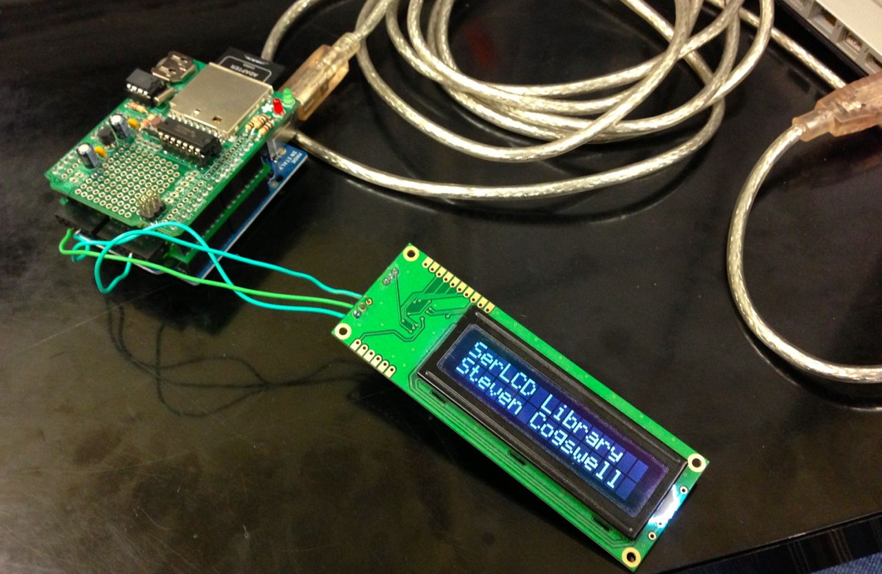


 and because apparently you’re not allowed to post about arduino on the intarweb without including a picture of an arduino, here’s


You must be logged in to post a comment.